An Artificially Intelligent Home
Explorations in Home Automation
Setting up Outdoor LED Strings in Home Assistant using WLED
January 4, 2026
Rather than spend hundreds of dollars on proprietary turnkey smart outdoor permanent holiday lights (or $thousands on profeesionally installed), I decided to try to use the same strategy that I used for indoor smart LED strings leveraging the WLED Project. The WLED project has very nice getting started instructions, including wiring examples, and tips to avoid common mistakes.
Going from small indoor strings to larger, more power-hungry, outdoor LED strings introduced a bit more complexity regarding power. I decided to go ahead and build a controller while investigating commercial systems.
I am by no means an LED or lighting expert - I am just reporting my experience and would welcome advice. I have no relationship with any of the vendors mentioned or linked here..
The best source I have found is the WLED Project itself (lots of tutorials and guides). The QuinLED website site also has lots of tutorial videos and pages.
TL;DR For a couple of strings you can get a nice turnkey controller to handle at least 150 LEDs in a string for about $25, and for about twice that you can get an even more fabulous controller for many strings and with fun expansion and integration features. Or you can spend about $15 to build your own. You’ll also spend about $10 for a 12 V / 5 A power supply if you go with a few strings, or $35 for a 12 V / 10 A power supply if you want many strings. I bought my 50-LED strings for about $15 each so for well under $100 you can have a system that is open and expandible and integrates with Home Assistant.
The LED Strings
I plan to mount my controller in the garage, 10-15’ from the closest LED string. From there, the longest distance is probably 50-60.’ I decided to go with 12 V rather than 5 V strings because they will draw less current for the same power, with much less voltage drop, especially with the extra 10–15 ft lead-in cables from a garage-mounted controller. The result should be more consistent brightness and color along the string, with fewer (or simpler, or I hope no need for) power-injection points.
I ordered some outdoor rated individually addressable LED strings, specifically some NovaBright WS2811 strings from Hollywood LEDs Many places sell these at very low prices, but I was looking for a domestic supplier to avoid shipping delays or tariffs, and Hollywood LEDs is in California.
These outdoor strings are powered by 12 V and the data line is 5 V. This means my controller must boost the 3.3 V data signal from the ESP32 5 V (especially given I’m using long (but not super long) cables to connect them, so this is all a bit more complex than the simple D1 mini driving a tiny LED strip.
Commercial Controllers
My exploratory DIY approach works for my particular setup but lacks the robustness, engineering insights that come from building multiple generations, and nifty features of the better commercial systems.
IoTorero Addressable Strip Controller (w/ built-in microphone) (WIP)
I ordered the IoTorero Controller from Athom Tech. I have ordered from them in the past as they have lots of nice HASS-friendly devices including Tasmota and WLED. They are in China but shipping is cheap ($7) and pretty quick (about a week). They are also very good at support, generally responding to email within a day or so.
The unit is turnkey and a nice solution for at least the 3 LED strings (daisy-chained, 150 LEDs) that I was able to test with.. It nicely drives my three LED strings, using a 12 V / 5 A power supply. It is also designed to control many types of LED strings/strips, including dumb ones. Upon arrival it boots in AP mode so you can connect it to your wifi (as described below in Attaching your WLED Controller to your WiFi Network).
The built-in microphone allows you to have your lights respond to music. In the WLED controller web interface you will see that some of the effects patterns show a musical note icon. These effects will respond to music picked up by the built-in microphone on this controller.
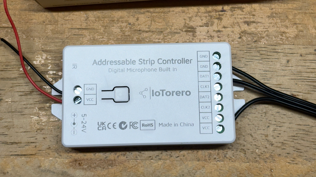
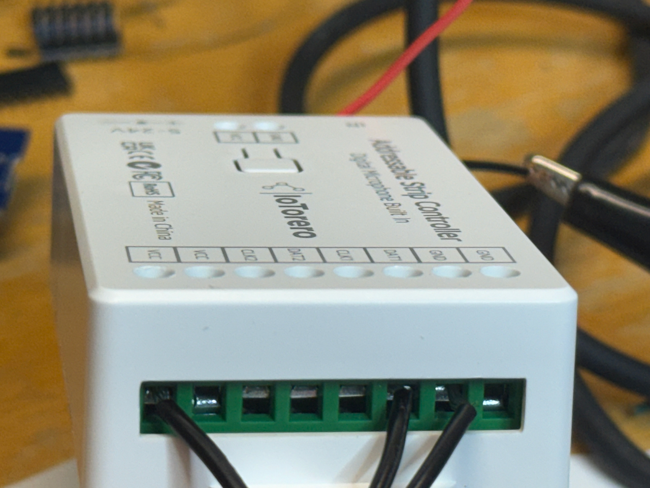
Above: Athom IoTorero WLED server (L) and wiring for WS2811 LED strings (R).
Dig-Quad
This controller has a very sturdy design and is ideal for my intended use with 4-5 50-100 LED strings (or more).. I ordered the QuinLED Dig-Quad from Dr. Zzs, an interesting online shop with gadgets related to Home Assistant, sensing, and LED power and control.
The Dig-Quad can drive four strings (or daisy-chained sets), each with its own physical connection. It’s got fuses on each channel for safety and comes in three flavors (antenna-on-board, external antenna, or (wired) Ethernet). All of the components, the board, and packaging are really solid, high quality. Very sturdy wire terminals. You can order a DIY version or a pre-assembled version. I ordered the pre-assambled.
Upon arrival it is supposed to have WLED installed but I did not check as there was at least some chance that I might need to update it anyway. There is an instaler link at the QuinLED website, taking you to the installation page where you will select your board and use the web installer to (re)install WLED. (You could also do this from the controller’’s wled web interface itself) After the install completes, the board boots in AP mode and from there you attach it to your WiFi network.
I was a bit surprised not to find any online quick setup guides, but the
site is an encyclopedia of information about all things LED-related,
with lots of videos and web pages. The website suggests going to their
YouTube channel. From there I searched for dig-quad and found their
Dig-Quad v3 introduction video
which provided a very nice engineering tour of the device.
I tested with my 12 V / 10 A power supply and my three LED strings. First I wired the three strings to individual (physical) channels, then I tried to daisy chain all three (150 LEDs) on one channel. Both cases worked great.
As fun as it was to build my own, this is the one I will use to drive my permanend outdoor strings. Partly this is because the Dig-Quad is designed for DIY extensions such as relays or external sensors.
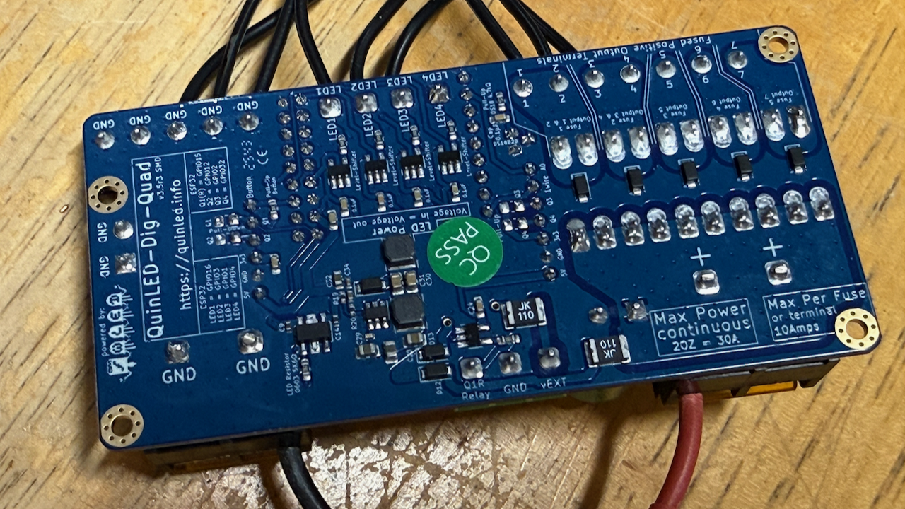
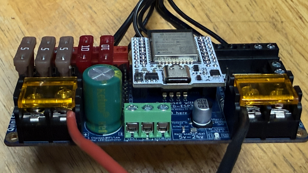
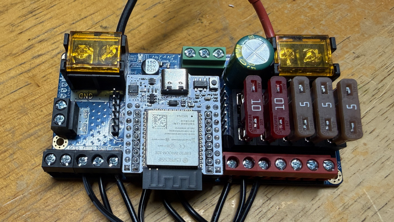
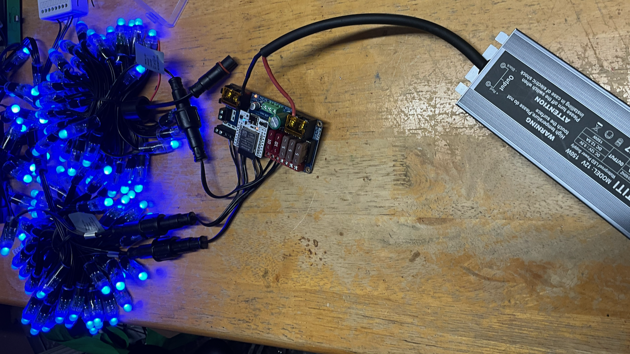
Above: QuinLED Dig-Quad. Various angle views and a shot of testing with 3 strings, total 150 LEDs. Worked fine on three separate channels or daisychained on a single channel.
Cool DIY features built into the Dig-Quad
The Dig-Quad has several nice features I’m eager to explore. It includes a built-in DS18B20 temperature sensor, which you can export to Home Assistant if you enable WLED’s MQTT feature (Config → Sync Interfaces). The sensor is located near the ESP32 header, so it mostly reflects board/enclosure temperature—which is exactly what you want for monitoring heat and safety.
The Dig-Quad also breaks out a handful of ESP32 pins on two small header rows so you can add “extras” without needing another microcontroller. These pins are logic-level I/O (not intended to power loads directly), so think: buttons, sensors, indicator LEDs (with resistors), temperature probes, etc.
Button (GPIO0)
The Button header pin is intended for a momentary pushbutton wired to GND, providing convenient local control right on the enclosure (no phone required). In WLED you can map that button to built-in actions such as toggle on/off, cycle presets, or brightness changes.
Note: GPIO0 is also used to put the ESP32 into boot/flash mode, so avoid holding the button while powering up unless you intend to enter flashing mode.
Q1 / Q2 (general-purpose GPIO)
Q1 and Q2 are general-purpose GPIO breakouts for low-current inputs/outputs (for example, reading a simple contact sensor or driving a small indicator LED through a resistor). If you’re switching something “real” (relay coil, PSU enable, etc.), use the Dig-Quad’s dedicated relay/output provisions or a proper driver module—don’t drive loads directly from a GPIO.
1-Wire + onboard temperature (DS18B20)
The Dig-Quad’s onboard DS18B20 is on the 1-Wire line, and the same header pin can also be used to attach an external DS18B20 probe. The onboard reading is best interpreted as board/enclosure temperature; for ambient temperature, attach an external probe and place it away from heat sources.
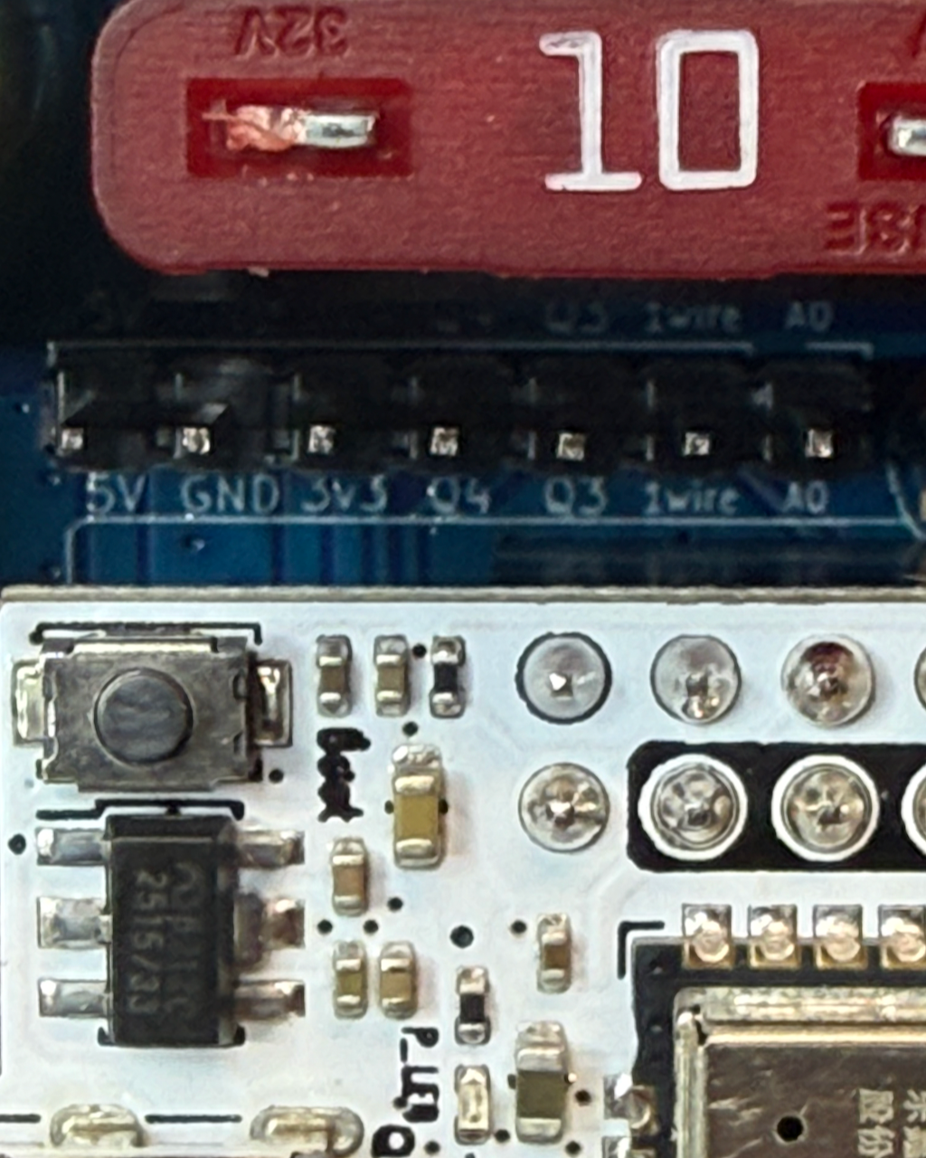
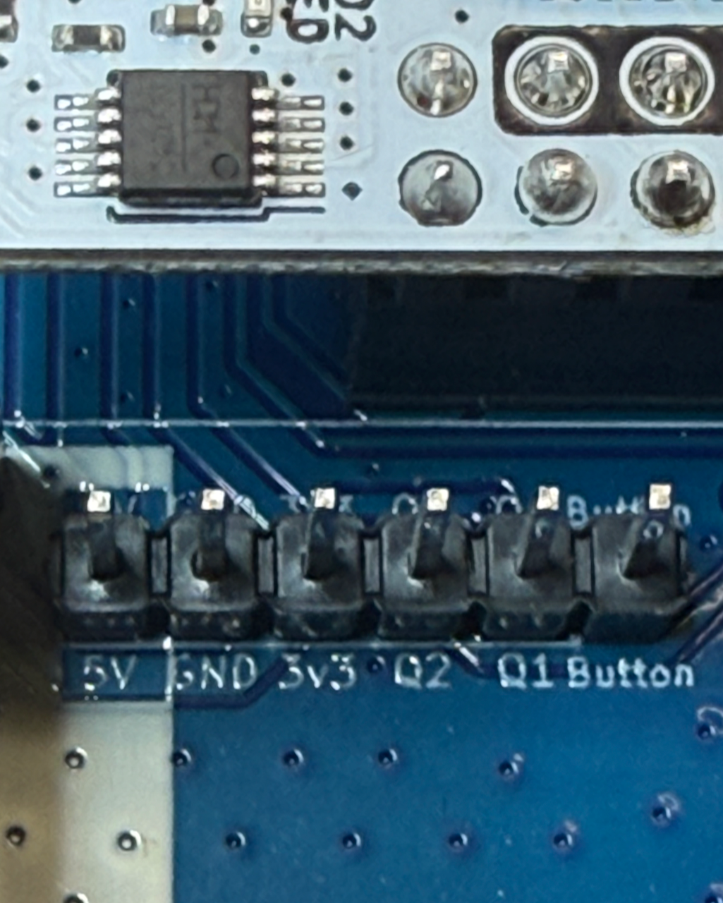
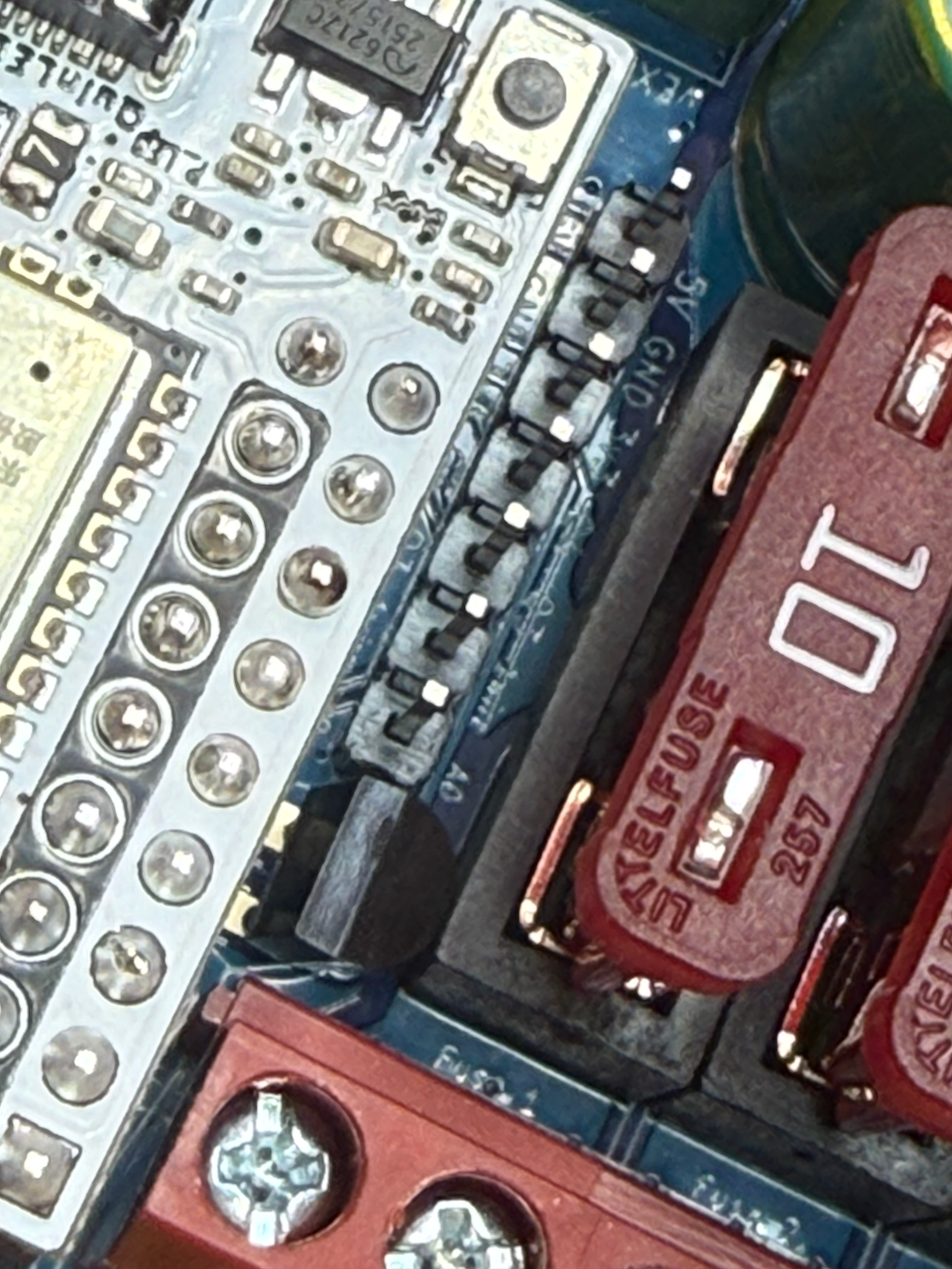
Above: QuinLED Dig-Quad close-up details.
(Left) Q4/Q3/1-Wire/A0 header (GPIO breakout + 1-Wire + analog in).
(Middle) Q1/Q2/Button header (GPIO breakout + optional local button).
(Right) Onboard DS18B20 temperature sensor (1-Wire), next to the A0 pin.
DIY Controller
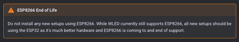
I started with the assumption I’d just tweak my previous WLED project using a D1 mini and in the process learned two things. First, there are multiple D1 mini flavors, and I accidentally ordered some with 1MB rather than 4MB memory. WLED will install just fine on the 1MB version but it won’t run. Second, even the 4MB memory D1 mini is a bit under-powered for anything but a small string of LEDs, and an ESP32 is much more beefy, while only costing $2 more (so why compromise?). The biggest reason to abandon the D1 mini for WLED is that the WLED project plans to stop supporting it:
Parts
Besides the LED string(s) linked above, I used the following:
- 5A Power Supply.
- ESP32 controller.
- 12v-to-5v Buck Converter. This is a bit bulky but it’s weatherproof and more robust - can handle up to 3 A whereas lower power / smaller form factor alternatives such as this are only rated for 1.8 A (fine for 1-2 strings).
- Logic level shifter (to boost 3.3 V to 5 V).
And I dipped into my inventory for:
- A 330 ohm resistor for each string directly connected to the board (I designed for two).
- Screw terminal block connectors (three 2-terminal and two 3-terminal).
- A 25v 1k uF electrolytic capacitor (goes on the LED-end of your cable).
- A 25v 0.1 uF ceramic capacitor (for the level shifter)
- A proto PCB board with power rails. Something like this should work - I could not find where I bought mine, but the main thing is you don’t want to mess with a straight-up stripboard (having to cut channels to place ICs, etc.).
Also, for any controller, we need to make cables to connect the strings to the controller:
- 3-pin waterproof LED (pixel) connectors (check to be sure these work with your LED strings).
- 18 Gauge 3-conductor cable.
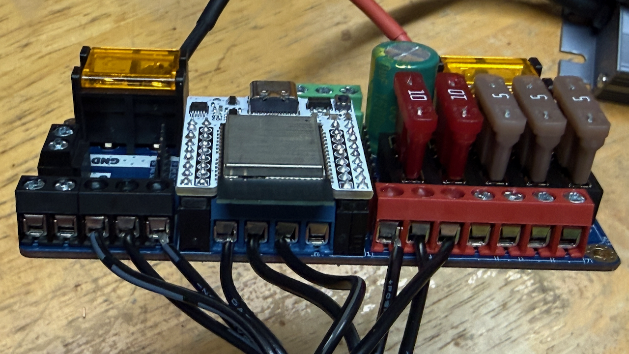
Fuses
The WLED guides and everyone else who knows about LED lighting all strongly recommend putting fuses in the power to the LED strings. I’m experimenting with a couple of different fuse strategies and will update the parts list when I find one that works for me. I have looked at full-size automotive blade fuses (as are used in the Dig-Quad) and mini-blade fuses. I could not find a fuse holder that was not bigger than I wanted, so I tried to go with the mini-blade fuses but I ended up with holders that were slightly too small for the mini-blade fuses to fit (so much for trusting the specs…).
Assembly
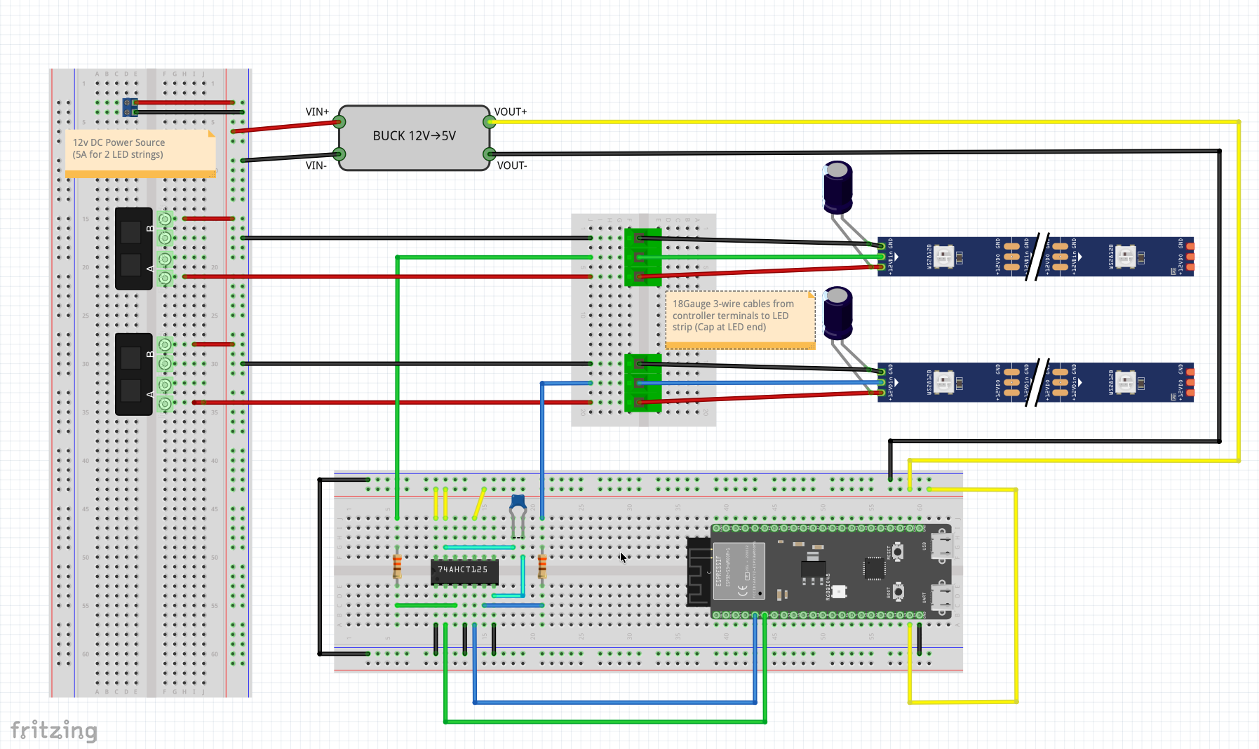
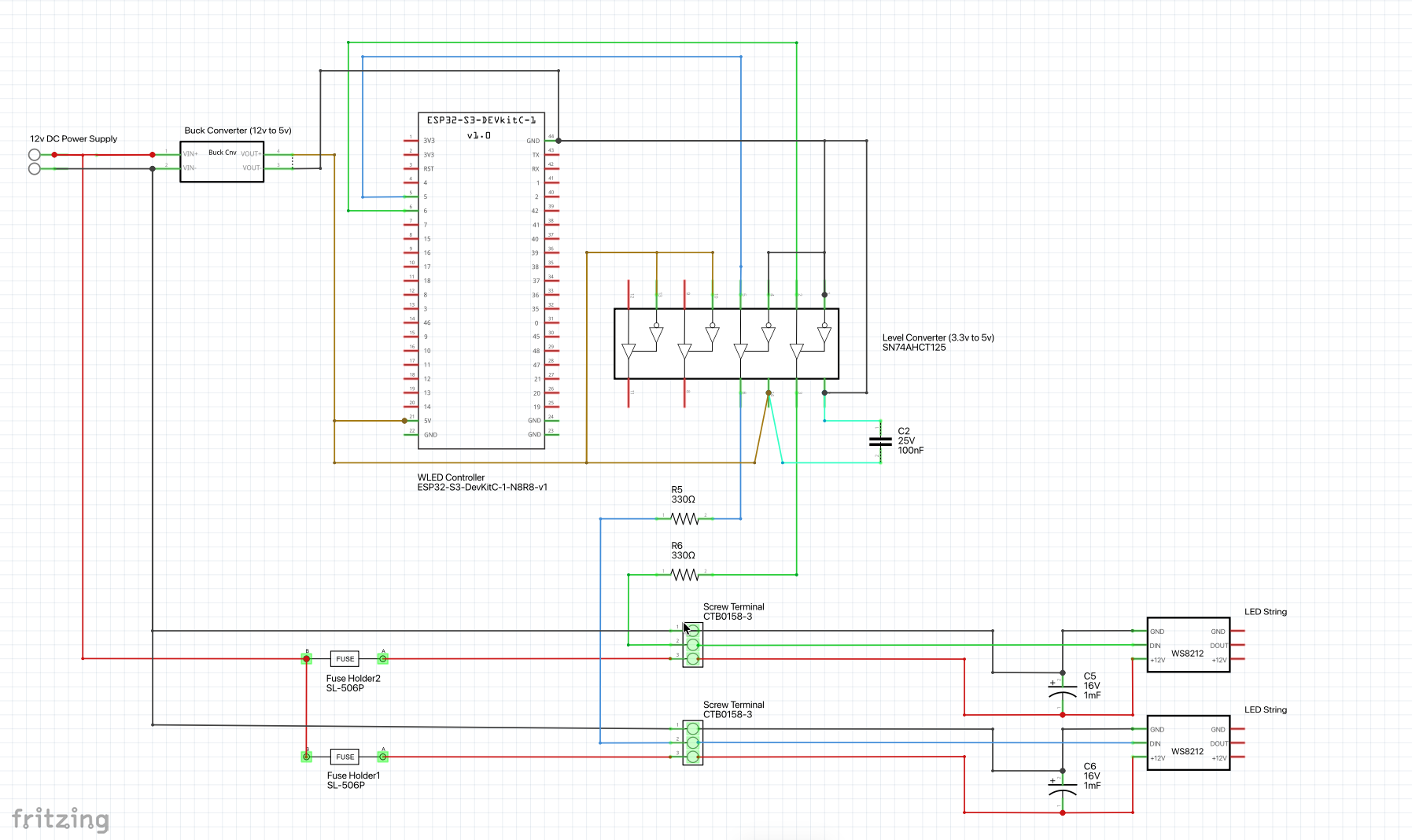
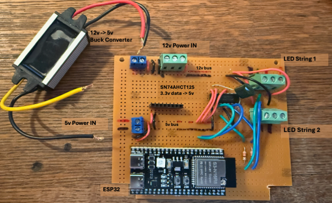
Above: How to wire this up. (L to R: Physical view; schematic; IRL). The IRL was my third layout, and I had run out of 2-port screw terminal blocks so used a 3-port for input (main) power at top left. You can also see the board includes a header for a D1 mini, which is not used in favor of the ESP32. Only one header was needed since we only used pins on one side (same with the ESP32). Finally, this picture was taken prior to my inserting the fuse holders in the 12v (+) paths to the LED strings. (Download the Fritzing file and custom parts)
Installing WLED
NOTE: For all of the WLED and WiFi attach instructions, I was tempted to remove because really you should go with the WLED Quick Start) guide. I advise going there, but some of the below may be useful so I’ll leave it in for now.
If you are integrating a commercial WLED controller you don’t need to install WLED (it’s already installed on your controller), so can skip to Setting WLED Controllers Up with Home Assistant.
If you built a DIY system you’ll need to install WLED. This guide uses ESP32-S3-WROOM-1-N16R8 as an example, but the same flow should work for most ESP32-family boards supported by WLED.
What you need
- A data-capable USB cable
- Chrome or Microsoft Edge (Web Serial is required for the installer)
- Your WiFi SSID + password
1. Put the board into flashing mode (important for some ESP32-S3 boards)
Many ESP32 boards auto-enter download/flash mode, but some ESP32-S3 dev boards require a manual step.
ESP32-S3 special steps (example: ESP32-S3-WROOM-1-N16R8)
- Unplug the board from USB.
- Press and hold the second button on the board (often labeled BOOT; not the Reset/EN button).
- While holding that button, plug in USB.
- Release the button after it’s plugged in.
The board will have a red LED that lights solid. If the green LED (or other) is blinking this means it’s running and not in boot loader mode (try the above again, holding BOOT for a few seconds after plugging in the board).
2. Flash WLED
Here you need a browser that supports Web Serial API (HTML serial). Chrome and Edge do; Safari does not. There is also a command line method for installing WLED if you prefer.
-
Open the web installer at https://wled-install.github.io/
-
Click Install (or similar) and select the USB serial device when prompted. Look for a device named something like /dev/cu.usbmodem1234 (or some other number). If you do not see the device it is likely that your USB cable is charge-only, so try a different one.
- Choose the correct target:
- Pick ESP32-S3 if you have an ESP32-S3 board (like the N16R8 example).
- For other boards, pick the matching ESP32 variant shown in the installer list.
-
If offered, choose Erase / Clean install (recommended for fresh boards or if you’ve tried flashing before).
- Start the install and wait for it to finish.
ESP32-S3 note after installation
- Manually press Reset/EN (or unplug/replug USB) after the installer completes.
- Some ESP32-S3 boards need that manual reset to start the new firmware.
Attaching your WLED Controller to your WiFi Network
As noted above, you should go with the WLED Quick Start) guide. I advise going there, but some of the below may be useful so I’ll leave it in for now.
After the reset, WLED should create its own AP (usually WLED-AP) when
it is not yet configured for your WiFi.
- On your phone/laptop, connect to the WiFi network:
- SSID:
WLED-AP(or something similar) - Password:
wled1234(if prompted)
- SSID:
- In a browser, open (http, not https):
- http://4.3.2.1 (not https)
-
At this IP address you should see the WLED web page for your controller. Click on the Config (gear) icon to edit your WLED controller settings and choose WiFi Setup.
-
Enter your WiFi network’s name and password. You can also change the mDNS hostname on this page for your WLED controller. [Note-1]
-
Click Save & Connect at the bottom of the page.
- Reconnect to your device via your home’s WiFi network. The easiest way to do this is to download the WLED mobile app. (iPhone/iPad, Android).
[Note-1] Once your controller connects to your WiFi you’ll need to find it. The easiest way to do this is to use the WLED mobile app. If you are not using the app, during step 4 above you may want to note its MAC address (unique hardware address comprising 6 pairs of hex numbers) or at least the rightmost 4 numbers. You can look for this in client lists on your home router to find the IP address of your device once it connects to your network. If you changed the mDNS hostname, you can also try connecting to yourControllerName.local.
Wiring & LED Configuration
If you have a commercial controller it will already be configured with the proper GPIO pin. But you still need to tell the controller how many LEDs are on each string (or daisy-chain).
If you went the DIY route, you’ll need to do this and map your strings to the GPIO pins we used for the DIY controller (pins 4 and 5 of the ESP32, which are GPIO4 and GPIO5, respectively).
In WLED UI:
- Go to Config → LED Preferences
- Set:
- LED Type: WS2811 (or the model corresponding to your string).
- LED Count: (the number of LEDs on your string, or total if you are daisy-chaining multiple)
- GPIO: Use the actual data pin (e.g., GPIO5 if you wired it that way)
- Set the Color Order: Most strings are RGB but I’ve seen WLED default to GRB. If your colors are not corresponding to their assignmenbts, e.g., the lights are green and you set them to red, double check the color order.
- Save and reboot
CLI Flashing
As an alternative to using the web installer,
you can install WLED from the command line using esptool
(esptool.py) on macOS, Linux, or Windows.
1. Install esptool
esptool requires Python 3. After installing, you can run it as esptool
(or more reliably as python -m esptool / py -m esptool if
PATH is finicky—especially on Windows).
macOS
Option A (Homebrew):
brew install esptool`
Option B (Python/pip):
python3 -m pip install --upgrade pip
python3 -m pip install esptool
Linux
Install Python + pip (command varies by distro), then:
python3 -m pip install --upgrade pip
python3 -m pip install --user esptool
Windows
- Install Python 3 and ensure it is on PATH.
- Then run:
py -m pip install --upgrade pip
py -m pip install esptool
If esptool is not recognized later, use py -m esptool ... instead.
Quick sanity check (all platforms):
esptool --help
or:
python -m esptool --help
or (Windows):
py -m esptool --help`
2. Download the WLED firmware (.bin)
Download the latest release firmware binary (.bin) from the WLED releases page, https://github.com/wled/WLED/releases.
- Go to the latest release
- Open the Assets list
- Download the
.binthat matches your board family (for example, choose an ESP32-S3 build if your device is an ESP32-S3)
Save the .bin somewhere you can reference from the command
line (or move it into your current working directory).
3. Erase flash (optional but recommended)
ESP32-S3 example:
esptool.py --chip esp32s3 --port /dev/cu.usbmodem1101 erase_flash
Port name examples:
- macOS:
/dev/cu.usbmodemXXXX - Linux:
/dev/ttyACM0or/dev/ttyUSB0 - Windows:
COM3(use--port COM3)
If esptool.py isn’t found, replace esptool.py with:
python -m esptool(macOS/Linux) orpy -m esptool(Windows)
Example:
python -m esptool --chip esp32s3 --port /dev/cu.usbmodem1101 erase_flash
4. Write the WLED firmware
ESP32-S3 example (adjust port and filename):
esptool.py --chip esp32s3 --port /dev/cu.usbmodem1101 --baud 460800  \
   write_flash -z 0x0 WLED_0.xx.x_ESP32-S3_*.bin
Replace WLED_0.xx.x_ESP32-S3_*.bin with the exact filename you downloaded.
5. Reboot and confirm
Press RST/EN (or unplug/replug USB). Wait for WLED-AP to
appear (it can take a bit), then proceed with the normal WiFi
setup steps in the earlier section.
Integrating WLED Controllers with Home Assistant
Once you have your WLED controller purchased or set up you can control it via its web page, but you will likely want to integrate it with Home Assistant. I recommend going to the Home Assistant WLED page for the best and latest instructions.
Enclosures
Neither the commercial units nor my DIY controller are weatherproof, but my plan has always been to keep the controller in the garage. Nevertheless I’d like it to be as weatherproof as possible, so my strategy for any of these controllers is to use a project box and proper grommets.
I bought a weatherproof project box that is a perfect fit for my proto-board (minus the notches I cut out on two corners. It’s deep enough that I will be able to run power in and LED cable connectors out with room for grommets. When that is finished I’ll update with specifics and more photos. And if course it would be fine for either of the commercial controllers I discussed earlier.
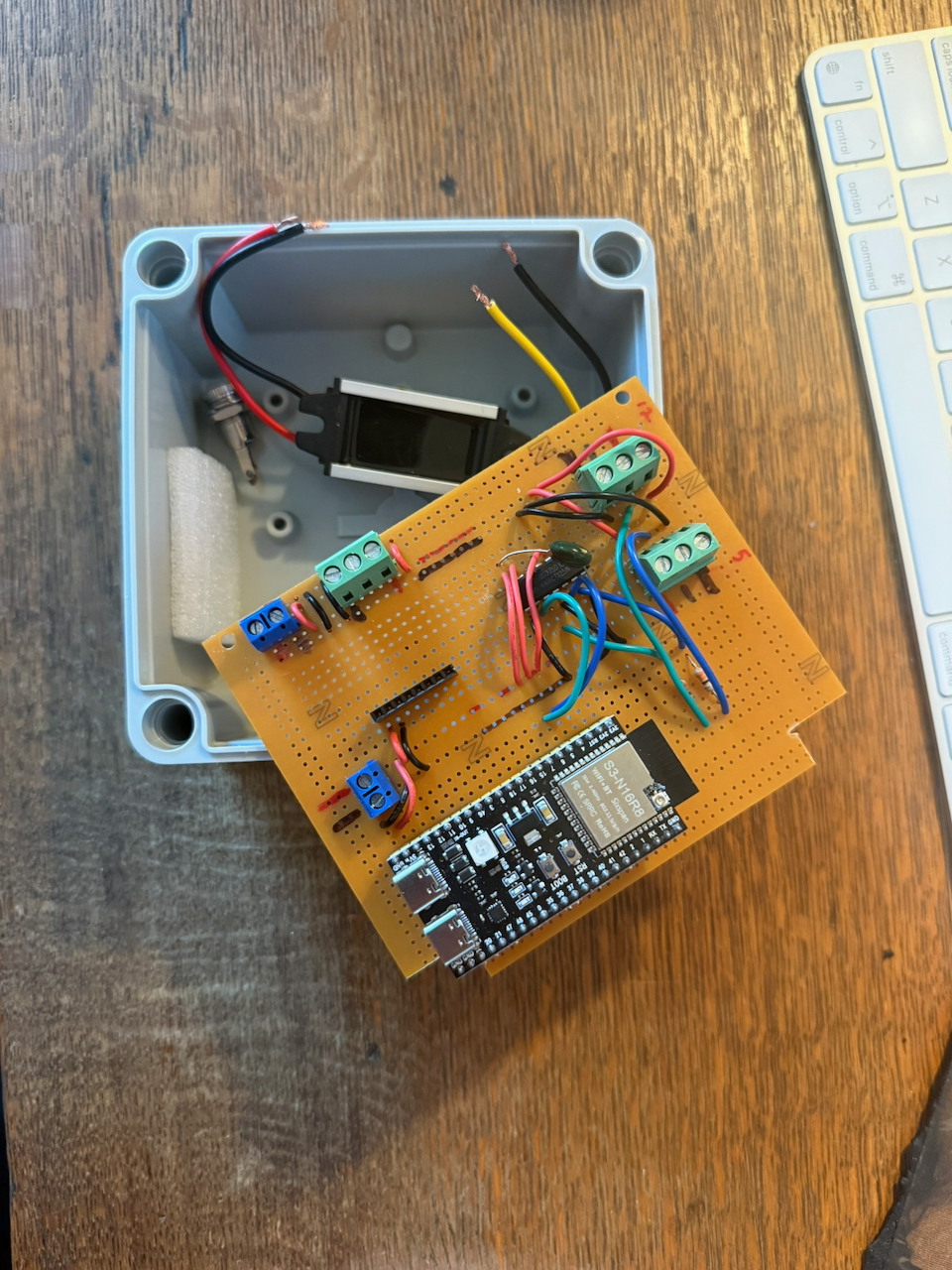
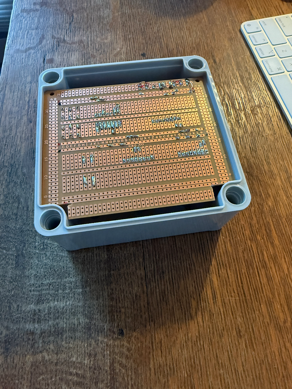
Above: WIP enclosing the DIY controller (and this size box should also work for the Dig-Quad).
Permanent Outdoor Mounting
When the weather is warm again I will permanently deploy about 100’ of LED strings for holiday lighting. I don’t really want to spend a lot of time with the mounting part. I found what looked like a nice solution (aluminum U-Channels with pre-drilled LED holes at 1” intervals) but the pricing is high and the shipping is outrageous (I tried to order a sample but the shipping costs were more than the sample cost, so I bailed on principle). When I find a solution I’ll update the post.
I plan to mount the controller in my garage, running 3-wire cables out to the LED strings, with distances of 10-20’ for each cable. The DIY approach above includes the connectors and cabling I am using.