An Artificially Intelligent Home
Explorations in Home Automation
Using a D1 Mini to integrate a Battery-powered Mini-LED String into HASS
December 22, 2025
We have various Christmas decorations that use mini-LED strings powered by AA batteries (typically 2xAA= 3v). I did not want to manually turn these on and off, nor replace batteries every few days. A D1 mini (at about $3) seemed like a good way to integrate something with very low power needs into Home Assistant (HASS).
These are dumb strings (not addressable such as you’d use with a more sophisticated project with WLED).
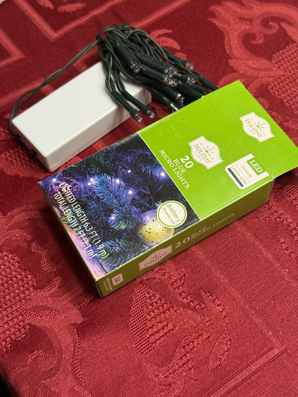
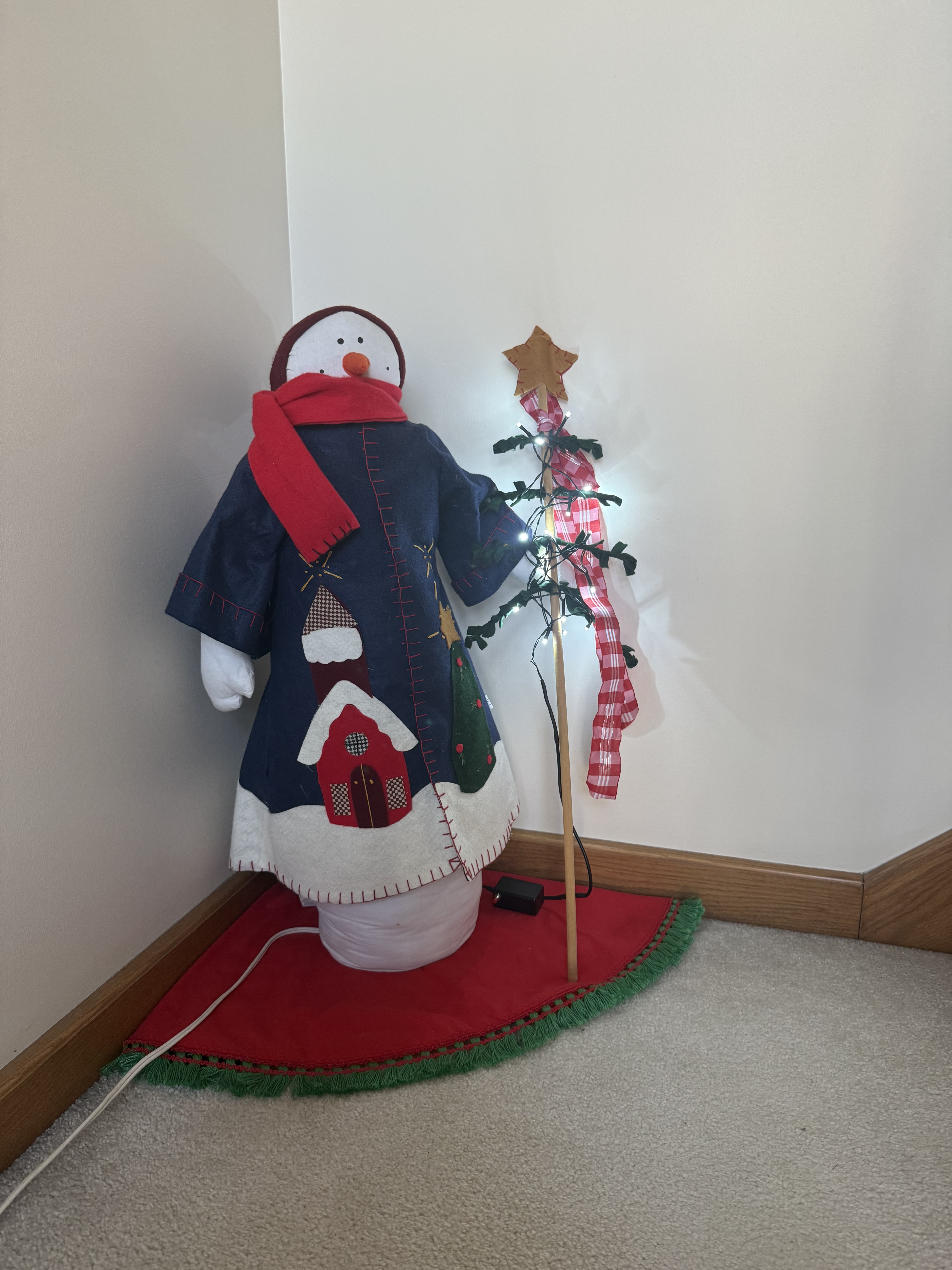
Left: a typical mini-LED set powered by 2xAA batteries (white enclosure). Right: D1 minigadget in action.
Hardware
Parts
- D1 Mini ($3) NOTE: If you were using WLED you’d want to be sure you are ordering units with 4MB memory. There are 1MB versions that cannot run WLED, but are fine for this very specific tiny application. They cost the same so if you are buying you should go for the 4MB versions, but if you have 1MB versions laying around, this is a decent use for them.
- Resistors (1k and 100k ohm). Pennies (if you are just getting started you should buy a kit with various sizes, such as this .
- A USB power adapter (e.g.,this or similar) and USB-A to micro-USB cable (e.g., .
- this (length is up to you dependong in what you need).
- A small signal NPN transistor (e.g., PN2222 or 2N2222, BC547, or 2N3904). Like resistors, these are pennies and you should get something like an Assorted Transistors Kit ($9).
- A mini momentary push button switch (normally open). Also cheap and worth stocking, e.g., this set of 12. ($8).
Assembly
I wanted this to fit neatly into a small enclosure, so I used a the small project box. I notched one end for the micro-USB plug, drilled a small hole at the other end to run the wires to the mini LED strip, and drilled a hole in the side for the button switch. (more on this below in Enclosures.
I have soldered up boards before only to accidentally fry the D1 mini, so I used headers. This was also handy because I had to cut the strip board small enough to fit in the project box, so the only place for connections was under the D1 mini (between the headers).
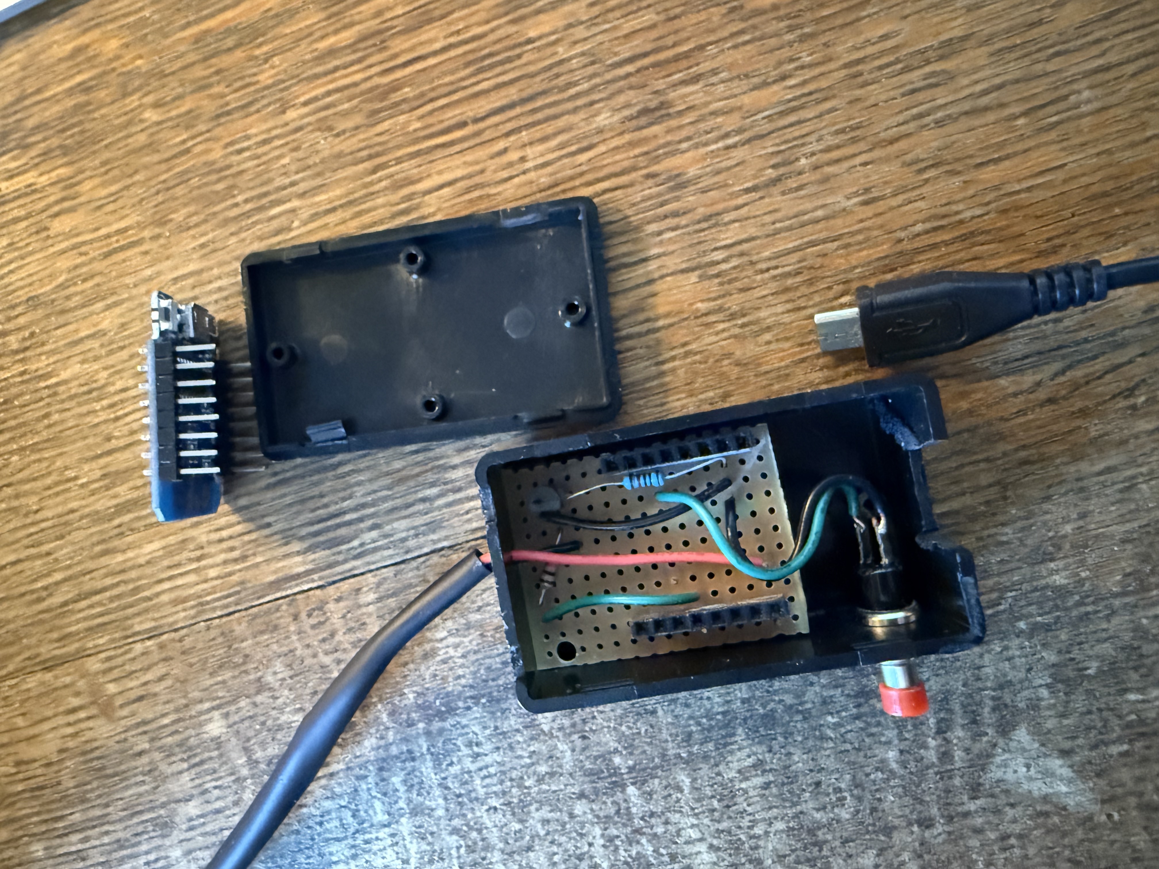
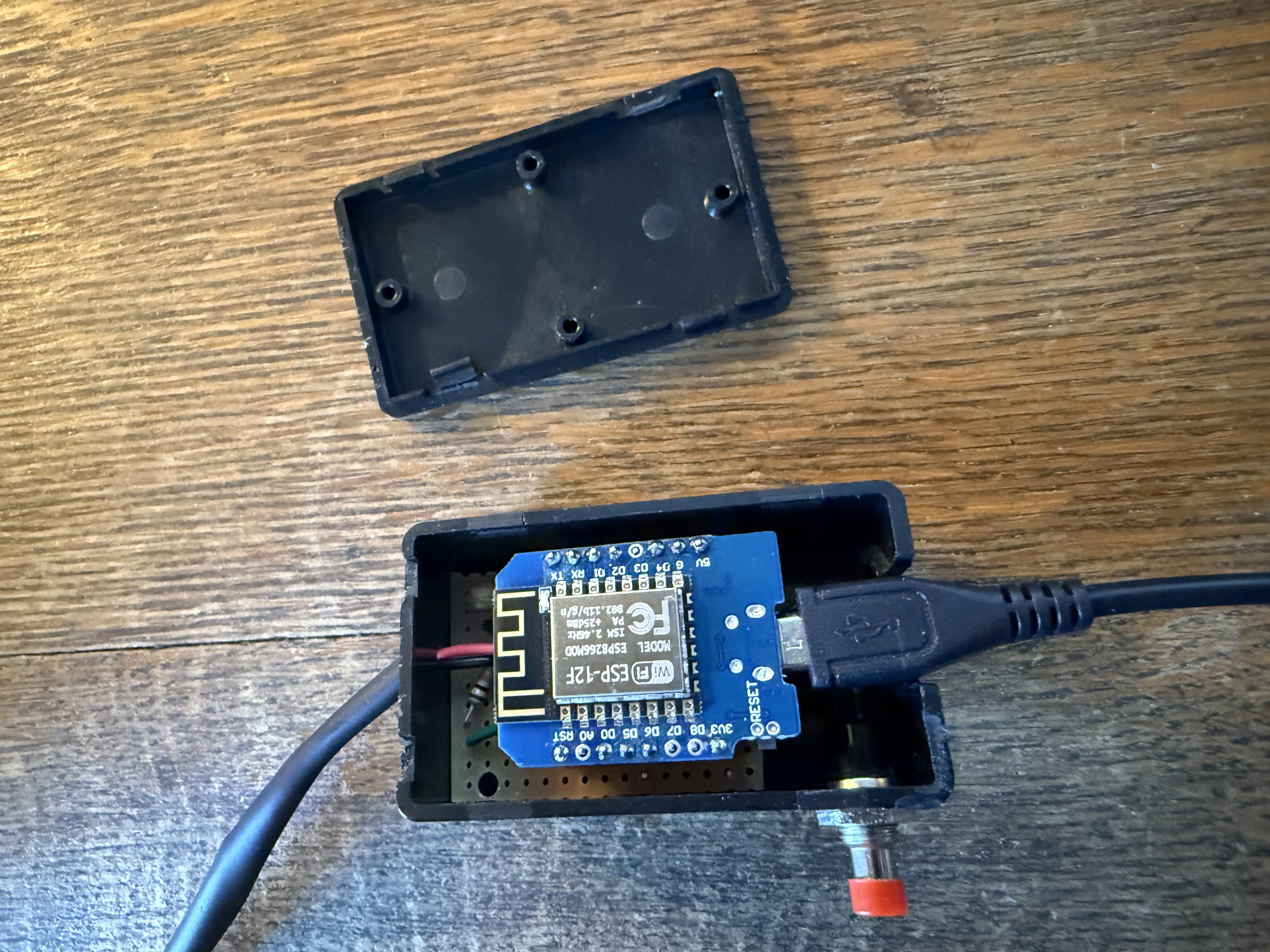

Above: Packaging (L to R: View of strip board; with D1 mini plugged in; finished project.
Wiring it Up
Wiring is straightforward as shown in the schematic and breadboard images below. We are using an NPN transistor and refer to the pins by their functions (Collector, Base, Emitter – C, B, and E). Your transistory data sheet will also number them 1-3 but the numbering is not consistent across brands.
D1 mini 3v3       ------------------------> LED string(+)
NPN Collector (C) ------------------------> LED string (-)

NPN Emitter (E)   ------------------------> D1 mini GND

D1 mini Pin D5    ---> [1k resistor] -----> NPN Base (B)
NPN Base (B)      ---> [100k resistor] ---> D1 mini GND

D1 mini Pin D1    ---> [switch] ----------> D1 mini GND

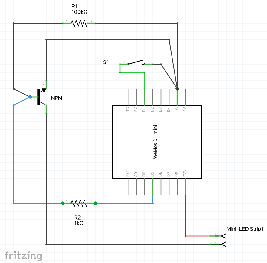
Above: How to wire this up. (L to R: Physical view; schematic; implemented with stripboard).
Set up with HASS
The steps below cover setting up a fresh Wemos D1 Mini to control a mini LED string using ESPHome and Home Assistant.
This setup process has two distinct parts. First, we use ESPHome to configure and securely flash the D1 Mini with a custom firmware — this includes setting up Wi-Fi, logic, and encryption keys. At this point, we have a device that powers the mini-LED strip with a push button toggle for on/off. But we want to remotely control and automate the mini-LED strip, so we need to integrate it into Home Assistant. Thus, we link the configured device into Home Assistant using the (ESPHome Integration) so that it becomes a manageable asset (with a UI card, device ID, and assignable area).
Prerequisites
- Wemos D1 Mini (ESP8266).
- Micro-USB Data Cable (Must support data transfer).
- Mac or PC with Chrome or Edge browser (Required for the initial web flash).
This entire procedure will be done with the D1 mini connected via USB to your computer. Make sure you have a cable that is for data and not just power (not all USB cables are equal). If your computer can’t see the device this is the most likely explanation.
Phase One: Initial Firmware Flash
Before Home Assistant can manage the device, you must install the base ESPHome firmware.
- Connect the D1 Mini to your computer via USB.
- Open web.esphome.io using Chrome or Edge.
- Click Connect and select the USB port for your D1 Mini.
- Click PREPARE FOR FIRST USE.
- Once it finishes and says Configuration installed! click CLOSE.
- Now it will attempt to connect to the device to set up WiFi.
If this fails:
- Press the reset button on the D1 Mini, then
- On web.esphome.io click the 3 vertical dots below CONNECTED and to the right of LOGS, and select Configure Wi-Fi then Connect to Wi-Fi (or change wifi if the device was previously connected).
- Select your WiFi network and enter your network password. If Wi-Fi Provisioning Times Out:
- Disconnect the D1 Mini from your computer and plug it into a USB power brick near your Wi-Fi router.
- On your phone or laptop, look for a new Wi-Fi network named Snowman Fallback or esphome-web-xxxx.
- Connect to that network and a captive portal page should open automatically.
- Select your Wi-Fi SSID, enter your password, and save. The device will reboot and join your network.
Phase Two: Create the Secure Identity in Home Assistant
- In Home Assistant, go to ESPHome Dashboard.
- ESPHome may show a discovered device and offer the option to Take Control
(also called “Adopt”). Don’t do this — it will try to rename the device and
assume it has been reflashed, which breaks OTA (over-the-air) updates for now.
Instead:
- Click + New Device at the bottom right. Click CONTINUE and
- In the Create Configuration window select New Device Setup.
- Choose any name (e.g.,
snowman) and - Select “ESP8266” as the device type. This creates a base configuration file in ESPHome we can safely edit before flashing.
- ESPHome now shows you the encryption key (no need to save it separately - it’s in the config yaml). Don’t waste time installing the generic build, just hit SKIP so we can add our logic before installing.
Phase Three: Add Snowman Functionality
- Click EDIT on the new
snowmancard. - Change friendly_name to “Mini-LED String” (or whatever you want).
- Copy the code below and (paste) append to the existing code.
- Click SAVE, then click INSTALL → Manual download. A log window will pop up and it will scroll for 3-5 minutes as it creates the build.
- When finished, the log window will report SUCCESS and
INFO Successfully compiled program. You can now select DOWNLOAD and
save the
.binfile (if you named your string snowman the file will be snowman.bin). You can CLOSE the log window and the yaml edit page to return to the ESPHome Buidler dashboard. - Open https://web.esphome.io in Chrome or Edge. Make sure you are connected to the D1 Mini - you may have to unplug/plug it in again to CONNECT from esphome.
- Click Install and choose the
.binfile you downloaded, then hit INSTALL..
# --- Snowman Logic ---

# Output: LED control via transistor on D5 (GPIO14)
switch:
  - platform: gpio
    pin: 14
    name: "Snowman Lights"
    id: snowman_lights_switch
    restore_mode: ALWAYS_OFF

# Input: Physical Push Button on D1 (GPIO5)
binary_sensor:
  - platform: gpio
    pin:
      number: 5
      mode: INPUT_PULLUP
      inverted: true
    name: "Snowman Button"
    id: snowman_btn
    filters:
      - delayed_on: 20ms
    on_press:
      then:
        - logger.log: "Snowman Physical Button Pressed!"
        - switch.toggle: snowman_lights_switch
Phase Four: Device Appears in ESPHome & Home Assistant
Once the device reboots after flashing, it will join your Wi-Fi as snowman.local.
It may take a couple of minutes to be discovered by ESPHome.
- You’ll see the device go online in the ESPHome Dashboard. Make sure to reload the page, as it likely still shows the original default named D1 (and you should still not click take control!). It may take a minute for the new device with the new name to appear online (you may need to hit its reset button).
- Go to settings – Devices & Services and you will also see the old
device as discovered.
- If you see the old (default esphome-named) discovered device at the top of the screen, use the 3 vertical dot menu in its upper right and DELETE it.
- Your new device should now appear, and you will want to ADD it.
- Once created, you will see the friendly name and can assign an area, then hit Skip and finish. (what we are skipping isn’t clear to me).
You’re done!
Pinout Reference
| Component | D1 Mini Pin | GPIO | Function |
|---|---|---|---|
| LED String | D5 | 14 | Connect to Transistor Base |
| Push Button | D1 | 5 | Connect to Pin and GND |
Phase Five: Future Management
- To update the code later, just click Install > Wirelessly.
- If you ever need to find your unique keys, they are safely stored inside that
snowman.yamlfile in theapi:andota:sections.
Optional: Moving Keys to Secrets (Clean Code Improvement)
Once your Snowman is running, you may want to move the auto-generated security keys into your secrets.yaml file. This keeps your main configuration clean and prevents accidental sharing of your private keys.
1. Prepare the Secrets File
Open /config/esphome/secrets.yaml and add these three lines:
snowman_api_key: "PASTE_KEY_FROM_YAML_HERE"
snowman_ota_password: "PASTE_PASSWORD_FROM_YAML_HERE"
snowman_fallback_password: "9KPSOTp0serw"
2. Copy and Paste
- Open the EDIT window for your
snowmancard. - Find the long string next to
encryption: key:and paste it into yoursecrets.yamlnext tosnowman_api_key. - Do the same for the
ota: password:.
3. Update the Snowman YAML
Now, update your api: and ota: blocks in the Snowman editor to look like this:
api:
  encryption:
    key: !secret snowman_api_key

ota:
  - platform: esphome
    password: !secret snowman_ota_password
4. Final Wireless Flash
Click INSTALL and choose WIRELESSLY. ESPHome will verify that the “secret” matches what is already on the chip.
Enclosures
The enclosure shown above in Assembly is a bit tight but I was able to fit this controller and an on/off switch into the small project box)
It was easy to just notch out a hole for the USB (for power) and drill holes for the switch and LED cable. But it would not take much of a tug to rip the wires out, so a bit of super-glue to fasten the cable to the enclosure would bot seal the hole and protect against accidentally harming the wiring. Also I think an improvement would be to snip the USB cable and find the DC power, running just the cable through as the micro-USB connector is huge relative to this device. Superglue would help there too.