An Artificially Intelligent Home
Explorations in Home Automation
Setting up LED Strips in Home Assistant using WLED
January 31, 2025
Recently we got bids for a kitchen remodel and some included an option to put under-cabinet lighting, which I think is kinda cool. They ballparked it at like $1,000 and who knows if their tech would even be smart enough to integrate with Home Assistant which to me is mandatory. Moreover, that price is pretty crazy.
Around the same time I heard about the WLED Project, so decided to try it out.
Below are the steps I took to get Home Assistant-controlled LED strips up and running. There is a small bit of soldering involved but nothing fancy. I’m going to link to the specific components I used as a courtesy in case helpful to you, but there may well be better options. I’m not an influencer so I get no kickback from the sources.
Also, the WLED project has very nice getting started instructions, including wiring examples, and tips to avoid common mistakes.
Hardware
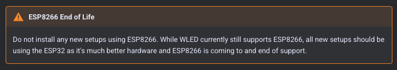
NOTE: Since this post was written, WLED has announced that they will no longer support the ESP8266 (chip used on the D1 Mini). Instead of the D1 mini as outlined in the instructions below, you should go with an ESP32 device. I use these for example. The cost is about $5 so only a few $ more than the $3 D1 Mini.
Parts
- D1 Mini ($3) NOTE: Make sure you are ordering units with 4MB memory. There are 1MB versions and these cannot run WLED.
- WS2812B/SMD5050 individually addressable LED Strip ($11)
- Self-adhesive LED strip mounting clips ($7 for 80)
- A 330 ohm resistor. You could buy 100 for $7-8 or you may as well get virtually a life-time supply of different sizes such as in a kit like this .
- Low-profile USB power adapter
- 1’ USB-A to micro-USB cables (you may need a different length; this was just right for the distance from the bottom of my cabinets to the wall outlets)
A note about fusing and power. With the above parts you’d think that driving 144 LEDs (~60mA each ~= 8.6A) would quickly smoke the power circuitry on the D1 Mini. The default setting for WLED (at least for the D1 mini) has an automatic brightness limiter to prevent the LED strip from drawing more than about 1A, so not to worry! If you decide to go with more powerful supply you can turn this off via the web interface to your WLED-enabled D1 Mini (i.e., after you complete the Set up with WLED instructions below). It’s near the top of the LED Preferences page.
Having said this, the WLED project does not recommend this route, and moreover recommends having a fuse on the power line(s) for the LED strip(s). I am experimenting (circa Jan 2026) with several options for adding fusing to this project without making it a huge box that is no longer easy to hide under the cabinet above the countertop.
Assembly
I wired a D1 Mini to the power the LED strip as shown in the schematic below but using the D1 mini’s micro-USB to power everything. If you want to drive multiple LED strips with a single D1 Mini you can wire up an external power supply to the same 5V and GND pins that the LED strip is connected to. The figures below show a barrel connector for this purpose if you decide that’s the way you want to go. If not, just ignore that component and its wiring.
We are using pin D4 (=GPIO2) on the D1 Mini, as this is WLED’s default for the data (control) line. If you use a different pin you can change the pin assignment via the WLED web interface: CONFIG –> LED Preferences –> “Data GPIO: (increment/decrement menu).
The LED strips I am using come with a tiny controller connected to the upstream end of the LED strip with a connector. They came with an extra connector and 3-wire pigtail (red=5v; white=GND; green-DIN). I soldered these wires to my D1 mini (with an in-line 330ohm resister on the green line) as shown in the schematics below (in which the LED strip pictured does not have a connector). Using this connector also ensures that you plug into the upstream end of the LED strip (see WLED common mistakes).
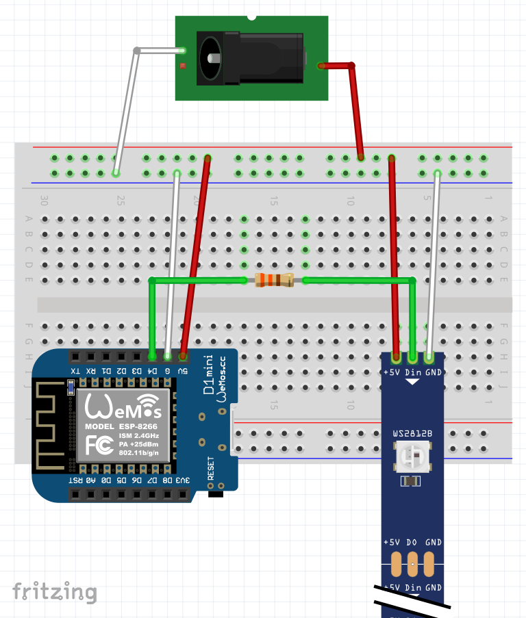
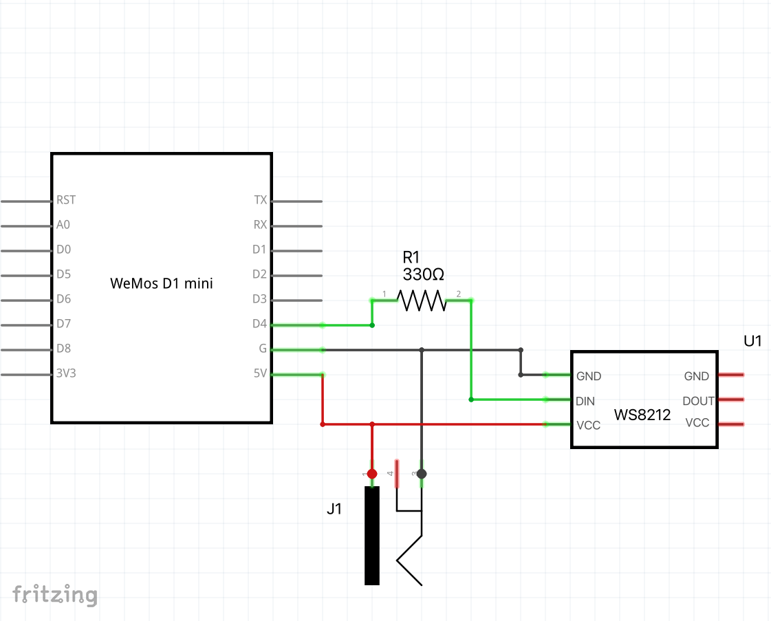
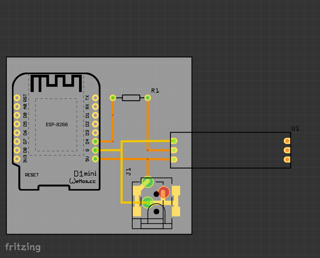
Above: How to wire this up. (L to R: Physical view; schematic; pcb layout). For completeness I show a barrel connector for power in case you wanted to go with an external, beefy power supply. One could readily hard-wire the power supply but a connector offers better flexibility (e.g., you may wish to swap out the D1 Mini or the power supply later). (Download the Fritzing file)
Set up with WLED
I was tempted to remove these instructions because really you should go with the WLED Quick Start) guide. I advise going there, but some of the below may be useful so I’ll leave it in for now. These were also written for D1 mini, which is no longer recommended (see note above - move to the ESP32).
-
Download WLED firmware from WLED Github repo. Go to the Assets section to find a list of firmware downloads and download the firmware for the D1 mini (I used WLED_0.15.0_ESP8266.bin).
-
Plug your D1 mini into a USB port on your laptop or server.
- Install the firmware on our D1 Mini.
- Open a web browser to web.esphome.io (it will tell you if your browser will work, or that you have to use a different browser).
- Hit Connect and Select the USB port your D1 Mini is plugged into.
- Select Install and point it to the firmware you downloaded. This will erase the D1 Mini and install the WLED firmware. (You can skip the “Prepare for First Use” option)
- The web page should report “Configuration installed!” and the blue LED on the D1 mini (next to the TX pin) will light solid blue.
- Connect D1 Mini to your WiFi.
After installing the firmware, your D1 Mini will now act as a WiFi access
point and will broadcast its WiFi network with an SSID (such as
WLED AP. Using a smartphone or tablet (rather than disconnecting
your computer from the Interent), connect to the WLED AP WiFi.
Open a browser (on the same device connected to the WLED WiFi network) and:
- Open http://4.3.2.1 (not https). If you are asked for a password, the WLED default is wled1234.
- This first page (with “Welcome to WLED!” at the top) will give you two
options: WIFI SETTINGS and TO THE CONTROLS!.
++ If you are using DHCP rather than hard-coding an IP address, I recomment noting the MAC address for the device Before setting up WiFi, To do this, TO THE CONTROLS! and at the top right of the WLED control page you’ll see an Info option - select that and jot down the device’s MAC address. This could come in handy later when you need to know its IP address, which you’ll need later for integrating the device with Home Assistant. - If you dove in to get the MAC address, hit BACK until you are back at the “Welcome to WLED! screen, and select WIFI SETTINGS
- The WiFi setup screen has a “Scan” button at the top- hit that and then select your WiFi and provide the password. for WiFi networks. Select yours and enter your WiFi password.
- You may want to name the device, so now scroll down on the WiFi Settings page to “mDNS address” where there will be a sort of random hostname starting with “wled-“. Especially for use with Home Assistant you should give this a descriptive name (aligned with whatever naming scheme you use for connected devices).
- Hit save and connect. The D1 Mini will reboot and attach to your WiFi network (unless you mistyped the password).
- To connect to the device now you’ll need to know its IP address on your WiFi network. Use your router or smartphone WiFi management app to do this (every system is different).
- Final steps
- Once you plug your D1 Mini (connected properly to your LED strip) in it should light up (if not, make sure you did not make one of these common mistakes)).
- WLED defaults to 30 LEDs in a strip, so you’ll only see part of your strip light up. Head back to the web interface (from step 4) and go to config -> LED Preferences and under LED outputs set the Length to the number of LEDs in your strip (the one in the parts list above is 144 LEDs). Hit Save and it should restart with the new settings.
Now you have a working WLED controller, so you can manually changes the LED colors, invoke dozens of patterns, etc. from a web browser. But don’t you want to automate this? I thought so. Read on.
Integrate with Home Assistant
This part is the easiest. First, install the Home Assistant WLED integration. Once you install it, select it and on the WLED page under Devices select ADD DEVICE and fill in the IP address of your D1 Mini. (check your router client list - here is where knowing the MAC address can be helpful). After adding my first WLED device, additional ones were auto-discovered so I did not need to know the IP address, which was quite handy!
The WLED project has good instructions to help with Home Assistant WLED integration.